Software

Overview
The software for the clock is written in C, and compiled using the free SDCC compiler. I have used the PUF USB Framework, which provices a USB firmware for easy interfacing to a PC, and also a bootloader for easy software upgrades, Naturally, the USB functionality can only be used when the motor is off! I have written and used a number of modules, which are detailed below.POV functionality
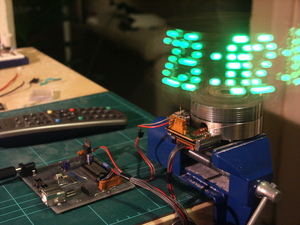
The actual drawing of the pixels is handled by routines which are based on the PICs Timer3 and RB5 port interrupts.The display is set to be 100 pixels wide. In order to draw the complete display, every 100th of a revolution the next row of pixels is displayed.
The Timer3 counter is set to overflow every 100th of a revolution, with the generated interrupt used to draw the next column of dots.
The firmware uses the RB interrupt, connected to the photointerruptor, to detect each revolution of the drum. By measuring how long it takes to make a complete revolution, the Timer3 counter gets updated with the precise value needed to generate interrupts 100 times per revolution. The display is therefore able to remain perfectly synchronised with the rotation.
An offset value allows the display to be shifted around the circle. Keeping this offset value constant shifts the display a fixed amount, whereas if this offset is changed regularly, the text appears to rotate around.
The text is displayed using a simple fixed width font. I created the font using a text editor, drawing 5x7 boxes and filling the pixels in. A simple Python script converts these ascii representations into hex values in a C file.
USB
The PIC features a USB controller - so why not make use of it?There are header pins on the board for USB, and I can hook this into a PC (whilst not spinning of course!). I use it for programming a new firmware onto the PIC, and also setting the time, setting messages, and other things that can be complicated over RC.
The USB stack is the Vasco USB stack which I also use extensively in other projects. It compiles using SDCC, and has a bootloader on board so that I can reprogram the PIC without using an ICSP.
The Vasco stack lets me access and use any of the endpoints for full USB functionality. On the host side, I use some simple Python scripts, and the Python USB modules.
RTC interface
The DS3232 chip uses an I2C interface. This is an industry standard two wire protocol - one wire is clock, the other is data. Whilst the PIC micro has built in hardware for talking I2C, I have used my own I2C stack, as it is really easy to use and I was too impatient to learn the PICs hardware. :) However I have left this as an option, as I am using the same pins that the hardware interface uses, so it should just be a software change.As well as time functions, the DS3232 has its internal temperature sensor accessible, so I read its register to get the current temperature. It also has around 220 bytes of user SRAM. I have used this space to store user messages (received over IR/bluetooth).
RC5 remote control
For the IR remote, I have attached a standard 3 pin IR receiver to an interrupt pin of the micro.I wrote an RC5 stack for the PIC, as most of the code floating around on the web is not up to scratch. My stack is based off this algorithm, and it uses proper timing verification for accurate decoding. Many of the algorithms around dont check proper timing, which can lead to spurious events.
The stack is written to be completely modular. I have used the same code in a few projects, and only need to change a couple of #defines. The C preprocessor takes care of the necessary timing calculations.
As well as reception, my stack also has an RC5 transmitter, so a project can make use of TX and/or RX using the same code. #defines ensure only the needed code is compiled in.
Motor control
The PIC that controls the base is responsible for regulating the drum motor. The AN6387 chip that I use adjusts its torque based on a reference voltage and a torque voltage. The reference voltage is set using a resistor divider, to around 1.8 volts. The micro then uses its PWM peripheral to adjust the torque voltage. A simple op-amp integrates the PWM signal and converts it to a DC voltage.
The AN6387, like any other drum controller, has an output that is
pulsed at a frequency proportional to the speed, in this case
the pulses are 6 per revolution. The PIC monitors this and can
adjust the torque PWM to compensate for speed variation.

Bluetooth
The bluetooth module provides a TTL RS232 interface, which is great as the PIC has an RS232 peripheral and TX/RX pins, so its easy to interface.
The serial/bluetooth CLI is currently a work in progress, but I have
written extensive serial CLIs for a PIC before, so it shouldn't be
too challenging.
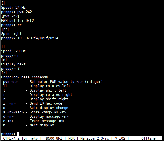
Update! I've now got a command line working over bluetooth! See
screengrab below - this is the device being controlled over bluetooth
and minicom. Numerous commands are supported.

Light sensor
The light sensor was an afterthought, as I had a small spot to fit it on the board. It simply is connected as a simple voltage divider from +5v, and the input pin is configured with the analog to digital module, measuring the voltage.