Hardware
Mechanical
The core hardware feature of this clock is the VCR drum. As described in the introduction, it provides a base for the clock, it rotates it, and it also has a built in mechanism for power. The PCB is mounted on top of the drum, held in place by the drum spindle and the connections soldered to where the heads connected to the transformer. The board also has two perpendicularly mounted horizontal bolts, which are adjusted to balance the board. When spinning at 30 revolutions per second, even a small mass imbalance can create lots of vibration. Most more recent VCR drums aren't as easy to use - the motor controller sits above the drum, making mounting of a board impossible by this method.Motor control
 VCR drums are brushless motors - as a result they require electronic
control. Because they also must be precisely timed to the video signal,
they also require signals to control the speed and phase.
I was fortunate enough to uncover a datasheet for the AN6387 that
controls this motor, and was able to get it working on a prototyping
board, with some help from tracing the VCR circuit. The picture to the right
is the original board I pulled the controller from.
The chip also provides outputs for measuring the speed of the motor,
so I'm currently working on getting a microcontroller to regulate the
speed.
VCR drums are brushless motors - as a result they require electronic
control. Because they also must be precisely timed to the video signal,
they also require signals to control the speed and phase.
I was fortunate enough to uncover a datasheet for the AN6387 that
controls this motor, and was able to get it working on a prototyping
board, with some help from tracing the VCR circuit. The picture to the right
is the original board I pulled the controller from.
The chip also provides outputs for measuring the speed of the motor,
so I'm currently working on getting a microcontroller to regulate the
speed.
Core design
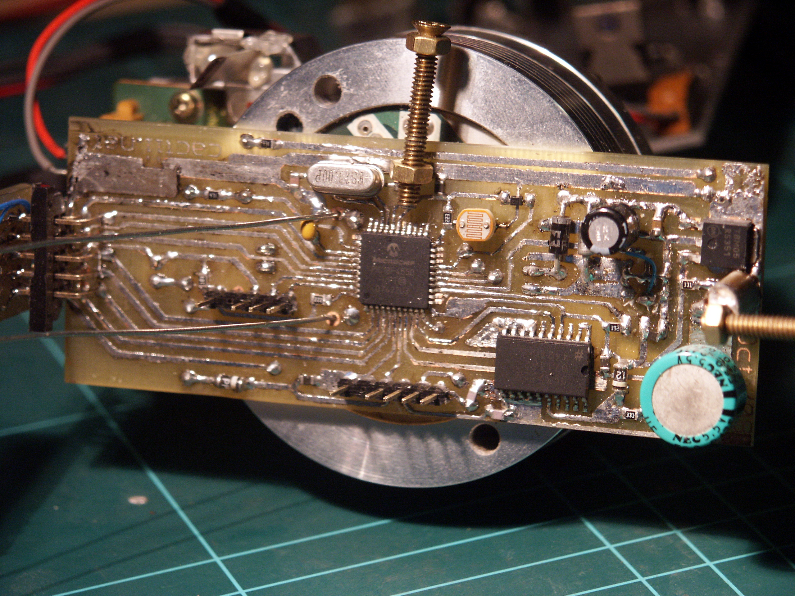
This clock is based around a PIC18F4550 microcontroller, which handles all the smarts as well as driving the LEDs. I found three 44 pin SMD devices on ebay for 9 euros, a real bargain. The micro also has a built in USB peripheral, so i can attach it to a PC and program it easily. A DS3232 RTC chip takes care of timekeeping, which I got as a free sample from Maxim. It has a supercap to keep it ticking if the power fails. A photointerruptor keeps the clock in sync with the rotation. I also added an LDR (light dependent resistor) to monitor ambient light, but I havent yet found a use for it.Power
In the base of the clock, a simple 555 based oscillator switches a power MOSFET at 100KHz, energising the rotary transformer's primary. The signal induced into the secondary is rectified by an FR104 fast recovery diode, then filtered and regulated down to 5 volts. I am able to get the necessary current to run the clock with this. I initially feared that there would be a lot of noise interfering with the micro, but this turns out not to be a problem.Timekeeping
A Maxim DS3232 RTC chip (real time clock) keeps track of the time. This is an I2C interfaced device, and it has a built in temperature compensated crystal oscillator to maintain time down to a second or so per month. It also has a 1Hz pulse output, which I interface with, and two alarms, which I can make use of. A supercap (from the same VCR as the drum) maintains the time when the power is off.Remote receiver
Setting the time on propeller clocks has always been a challenge. It's a little tricky to press buttons when it's spinning at 30rps...so I got the remote receiver from the VCR and interfaced that to the micro. A library I wrote for the micro allows me to receive RC5 remote codes, and use them for control. As well as changing the time, I can control a host of other parameters through it.Remote transmitter
I had room on the board, so I added two infrared LEDs to it. These are controlled by the micro, and I can send RC5 remote codes using them. This will be used to do such things as controlling the motor - if an alarm is set and goes off, the base can be sent a command to start turning. I have mounted two parallel LEDs on opposite sides of the board, to ensure even transmission of the signal to the base.Rotation synchronisation
It's essential that a propeller clock be synchronised with its rotation, so that the pixels can be displayed in the exact position in space without drifting. My clock uses a photointerruptor salvaged from a VCR, and a small vane mounted on the fixed base. The interruptor is triggered once per revolution, which the micro software uses for synchronisation.Bluetooth
I want to use the display as a type of interface to a PC, so to give me maximim flexibility regarding placement of the clock, I have a Sparkfun Bluetooth Module attached to the base. This will allow any script on a PC to send messages and other commands to the clock for display.Due to limited board space, I was not able to put the module on the rotating part of the clock. Instead, I have the module in the base. Anything sent over bluetooth will be transmitted to the rotating part using IR.